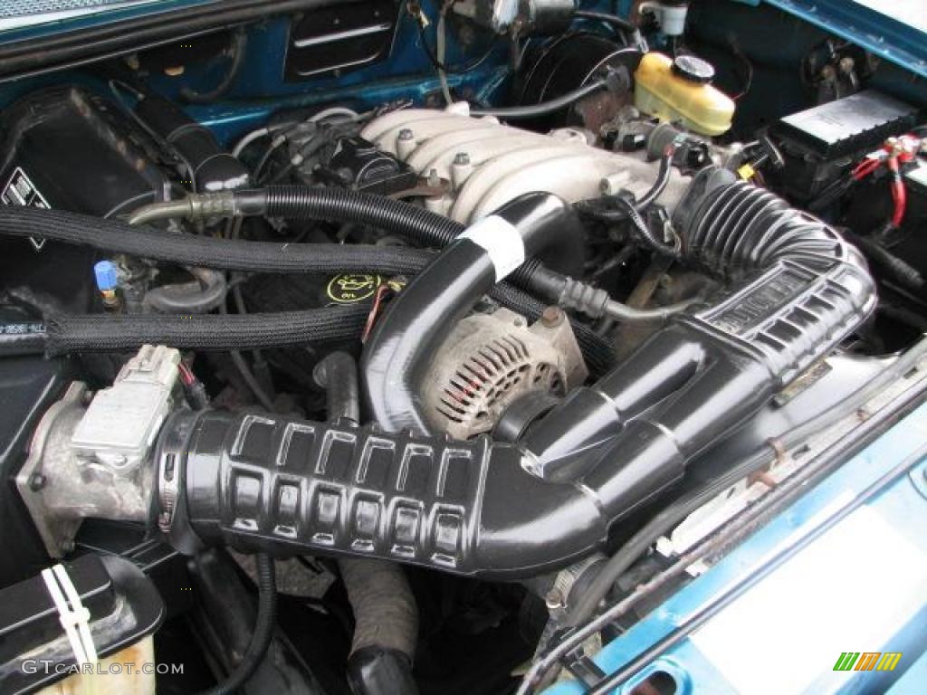

PFE – (O, R, M) PFE signal is/was low – PFEģ2 – EVP – (R) EGR not responding properly during test – EVP There are pictures under the different headings to help you identify the system.ģ1 – EVP – (O, R, M) EVP signal is/was out of range – EVPĮVR – (O, R, M) EVP signal is/was low – EVR If you don’t know what type of system you have, go to the EVP heading, which is the first one. PFE is for vehicles with Pressure Feedback EGR (PFE) sensor and and an EGR Vacuum Regulator (EVR)

Transmission Oil Temperature (TOT) sensor out of range – TransmissionsĢ8 – Vane Air Temperature (VAT) sensor out of range – VATĢ.3L w/Electronic Ignition – Cyl ID, IDM low or right coil pack failure – Ignition SystemsĮGR CODES DEPEND ON WHAT SYSTEM TYPE THE VEHICLE IS EQUIPPED WITH:ĮVP is for vehicles equipped with EGR solenoid(s), with or without an EVP sensorĮVR is for vehicles equipped with an EGR Vacuum Regulator (EVR) and an EGR Valve Position (EVP) sensor (R) Erratic idle during test (reset throttle & retest) – Idle Set ProceduresĮlectronic ignition Cylinder ID sensor/circuit problem – Ignition SystemsĢ1 – Engine Coolant Temperature (ECT) sensor out of range – ECTĢ2 – MAP (vacuum) or BARO signal out of range – MAPĢ3 – Throttle sensor out of range or throttle set too high – TPSĢ4 – Intake Air Temperature (IAT) or Vane Air Temperature (VAT) sensor out of range – IAT VATĢ5 – Knock sensor not tested (ignore if not pinging) – KSĢ6 – Mass Air Flow (MAF) or Vane Air Flow (VAF) out of range – MAF VAF (M) Ignition TACH signal erratic – Ignition Systemsġ9 (O) No Vehicle Power (pins 37 + 57) or bad PCM VPWR Diagnosis (O) Electronic ignition – IDM circuit fault – Ignition Systemsġ7 – 1.9L & 2.5L – Throttle stop set too low – IDLEġ8 – (R) Check base timing & advance function – Timing Tests (M) KAM (pin 1) was interrupted (was battery disconnected ?)ġ6 – 1.9L & 2.5L – Throttle stop set too high – IDLE or Idle Set Procedures (M) ISC sticking, open ITS circuit or TP stickingġ4 – Ignition pickup was erratic – Ignition SystemsĮ4OD Transmission diesel RPM sensor – Diesel RPM sensorġ5 – (O) No Keep Alive Memory power to PCM pin 1 or bad PCM (Memory Test Failure) (R) Idle Speed Control motor or Air Bypass not controlling idle properly (generally idle too high)

#1990 FORD ENGINE CODES CODE#
Disconnecting the battery will also erase all the codes however, this may trigger a code 19 (loss of PCM power).ġ2 – Idle Speed Control motor or Air Bypass not controlling idle properly (generally idle too low) – ISCġ3 – (O) ISC did not respond properly (extends to touch throttle then retracts for KOEO) – ISC Starting the memory test procedure, and unplugging the connections erases memory codes. Erasing Codes (2)Ĭodes automatically erase after 60-100 starts. The codes will be soon to follow, as per the previous test. When this happens, the throttle must be depressed (a minimum) of 25%. Eventually there will be a single quick sweep of the needle this is the throttle goose test. A timing light may also bee hooked up, and the timing should advance by 20 degrees during this test. The computer will test items, including the timing. The code reader will flash twice (for a four cylinder) three times (for a 6 cylinder), four times (for and 8 cylinder), and five times (for a diesel). This test is complete when code 11 (system pass) has been displayed. A 2 or three digit code will be several quick sweeps (1-9) followed by a 1 second pause, than the next number. Codes will be displayed as needle sweeps in groups of 2 or 3, followed by a 6 second delay. Once the multi-meter is attached, turn the ignition on, and watch the needle.
#1990 FORD ENGINE CODES MANUAL#
You want to make sure the engine is fully warmed up, automatic transmission in park, or manual transmission in neutral, with the parking brake on, or the wheels blocked. A jumper wire is also necessary (as below). The Positive lead of the multi-meter can be attached to the battery’s (+) terminal, and the negative lead of the multi-meter can be attached to the connection as below. An easy way to utilize this terminal without an expensive scan tool is with an analog multi-meter, set on DC Voltage (20V setting, or nearest equivalent). It is usually red or gray in color, and has a distinctive shape as shown below. On the passenger’s side, under the hood, there is the computer’s self-diagnostics output terminal.


 0 kommentar(er)
